TouchDesigner, Pixelmapping + DMX
Download the td_pixelmapper.toe file from the TouchDesigner Examples folder on Google Drive.
Download the pixelMapper.tox component from the TouchDesigner Examples folder on Google Drive.
Download and install the Advatek Assistant Software for macOS or Windows
What is DMX?
DMX is a protocol standard for communicating with and controlling “addressable” lights. This is the standard communication protocol for theatrical lighting, stage lighting and most architectural lighting.
From Wikipedia: DMX512 (Digital Multiplex) is a standard for digital communication networks that are commonly used to control stage lighting and effects. It was originally intended as a standardized method for controlling light dimmers, which, prior to DMX512, had employed various incompatible proprietary protocols. It soon became the primary method for linking controllers (such as a lighting console) to dimmers and special effects devices such as fog machines and intelligent lights. DMX has also expanded to uses in non-theatrical interior and architectural lighting, at scales ranging from strings of Christmas lights to electronic billboards. DMX can now be used to control almost anything, reflecting its popularity in theaters and venues.

Some Facts:
- DMX can control up to 512
channels. - Each channel has 256 steps of resolution (0-255).
- Each group of 512 channels is called a
universe - DMX is a “bus” protocol, which means that with every frame, a DMX
controllercommunicates all of its channel information. - Each
slave deviceis has astart address, and only listens to the parts of the DMX packet that pertain to its address. - Standard DMX is traditionally transmitted with 3-pin or 5-pin XLR-style cables and connectors.

What is sACN E1.31?
DMX can be sent over a network as well. There are two ways of doing this. Art-Net is the older and less robust protocol. E1.31 Streaming ACN (sACN) is newer, easier to use and more robust. We will be using sACN to communicate between TouchDesigner and our PixLite controllers.
What are Addressable LEDs
It is important to know that most “addressable LEDs” do NOT use the DMX protocol. Most “addressable LEDs” require some piece of hardware to sit between them and a DMX controller. In our case, we will be sending DMX over sACN to our PixLite controllers. The PixLite controllers will then translate our DMX signal into another protocol that the LEDs can understand.
LED Addressing
The LED strands that we are using are addressed sequentially, starting from the “pixel” that is nearest to the PixLite controller.
Pixel Mapping in TouchDesigner
The goal of this tutorial is to understand one method for transferring video content (live, prerecorded, generated) to physical LED “pixels” in physical space. We want to “map” the video content to the pixels, retaining the motion of the video by sampling the video at points relative to the spacing and arrangement of the physical layout of the pixels. To do this, we will follow these steps:
- Export polyline geometry in the OBJ format. Each point of the polyline corresponds to an LED pixel location.
- Import OBJ to TouchDesigner and use the locations of the vertices to sample video.
- Transform color sampling data to DMX data
- Send DMX over a network to a PixLite controller
- Set up a PixLite controller to listen to DMX and communicate with our addressable LEDs.
This tutorial will not cover step 1. For best results:
- always export your polyline with positive coordinates.
- Before exporting, place your geometry as close to the origin (0,0) as possible.
- Work in the XY plane.
- I like to make (but not export) a bounding box of my polyline geometry to better understand the dimensions of my geometry (total width and height of geometry).
Steps 3 and 4 are taken care of in the pixelMapper.tox.
Using the pixelMapper TOX Component
This custom component has two inputs:
- SOP input for linking your imported OBJ pixel locations
- TOP input for linking your source texture/video content
And one output
- TOP output that allows you to preview or simulate what the lights will look like after mapping.
To start, create a filein SOP and, in the Parameters pane, click the + button to choose the correct OBJ file from your computer. Link this SOP to the SOP input on the pixelMapper COMP.
Next, create a simple TOP (i like to use my webcam to test) and connect that to the TOP input of the pixelMapper COMP.
Finally, create a null TOP and connect it to the output of the pixelMapper COMP.
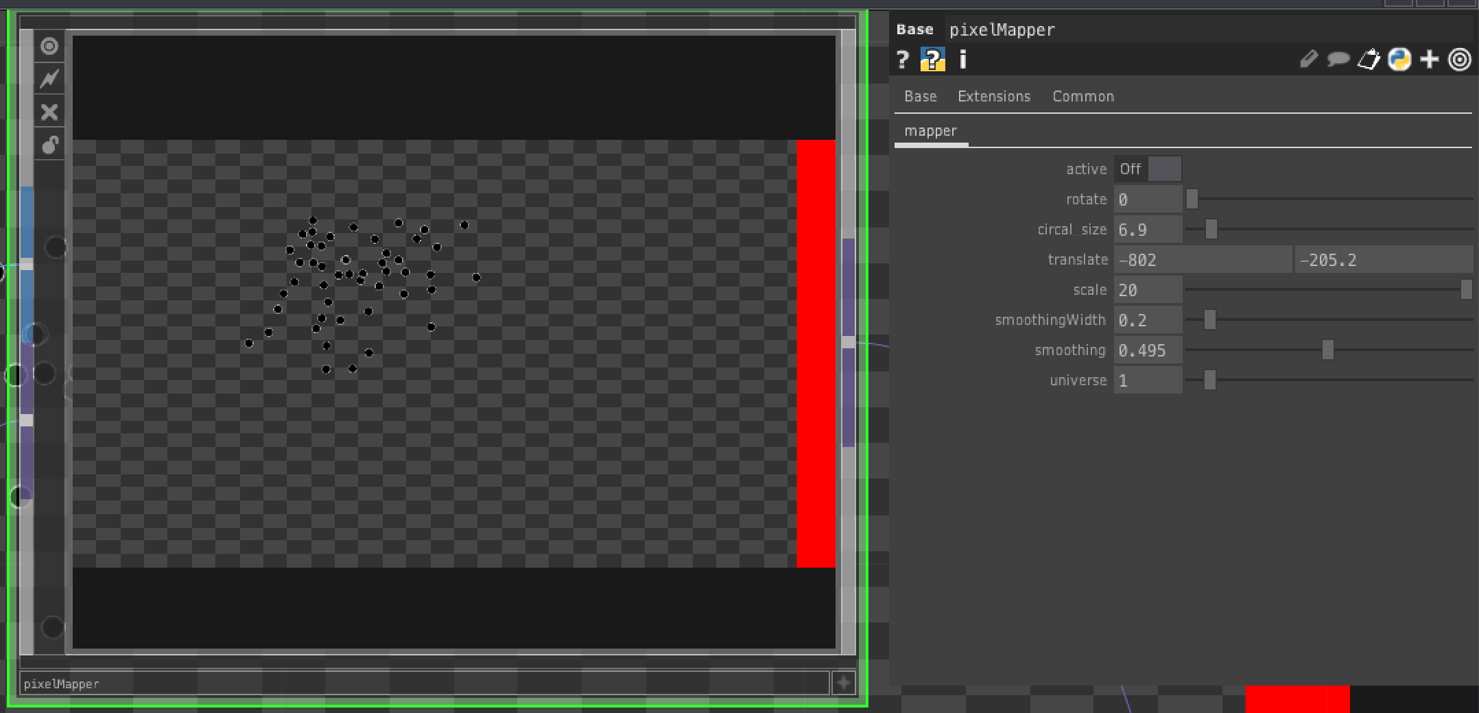
Lets look the Parameters of the pixelMapper COMP:
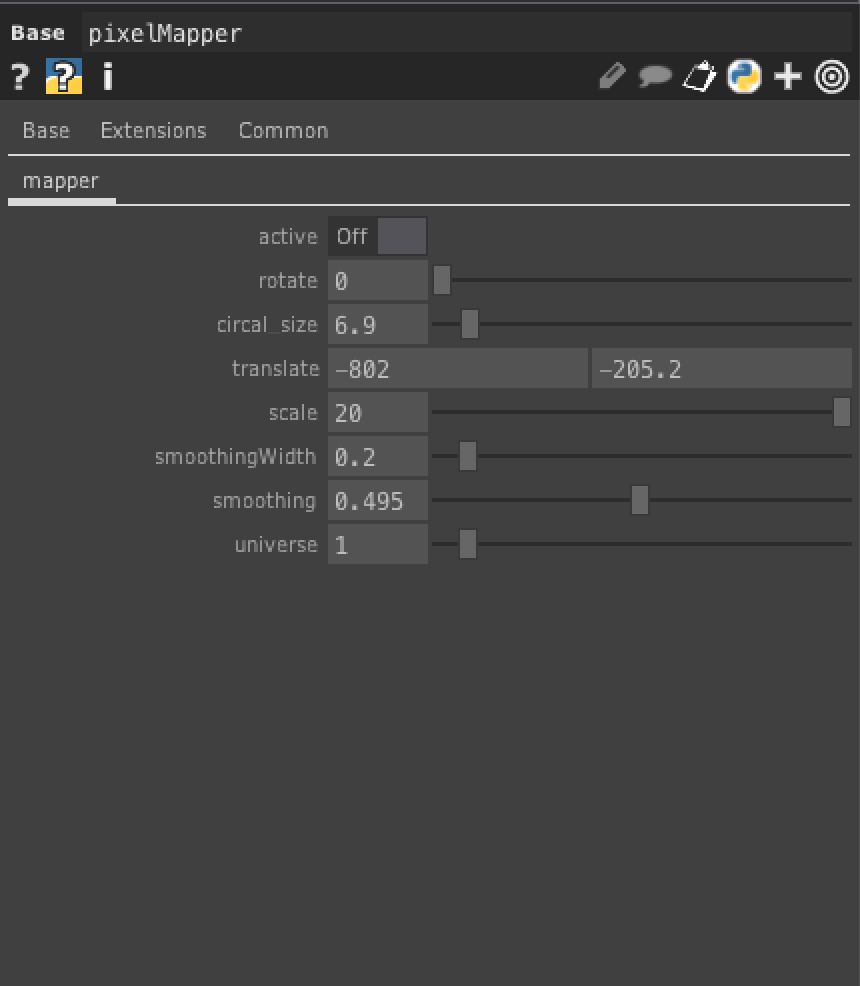
active - this turns the active sending of DMX on and off
universe - this is the DMX universe that we want to use (more on this later)
scale, rotate, translate - allow you to move your pixel points over your input video to get the correct mapping
smoothing parameters - allows you to smooth the signal, so you don’t get much of the jitters that come with video-LED processes
Setting up the PixLite Controller
If you want to get a deeper understanding of the PixLite Controller, have a look at the manual.
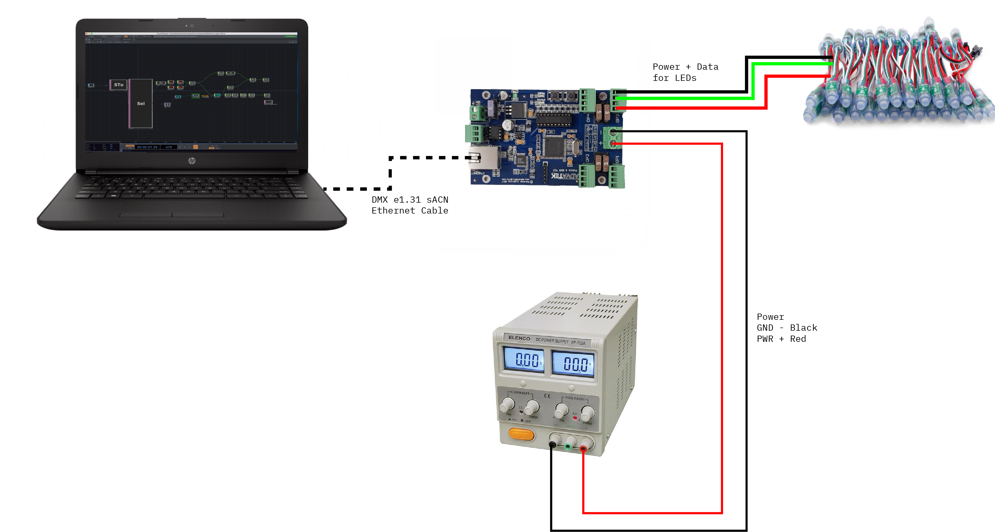
Physical Setup
Parts
- Variable voltage power supply
- PixLite controller
- Ethernet cable
- LED strand
- Two small screwdrivers
- male/male jumper cables
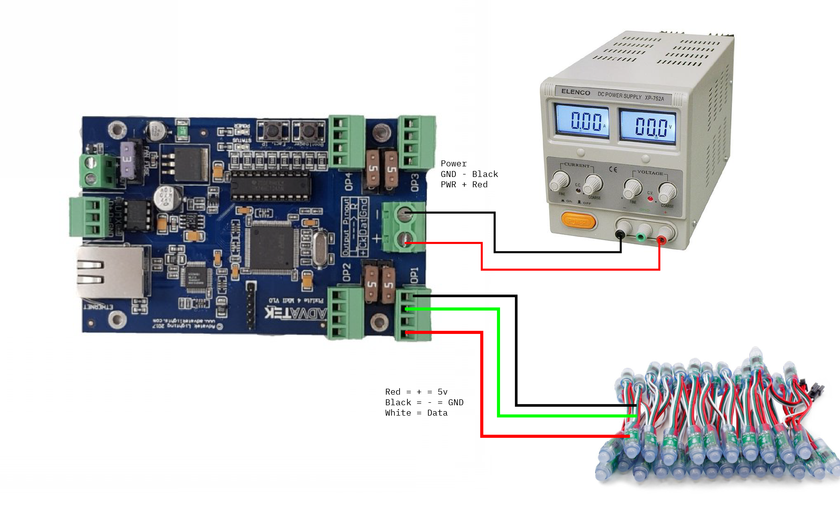
Connections
- Set the power supply to 5 volts
- Connect the power supply to the PixLite
- Use jumpers to connect the female end of the LED strand to
OP1of the PixLite- Red = +
- Blue = GND
- Whie = Dat
- Connect the PixLite to your computer via an Ethernet cable
Network Setup
macOS
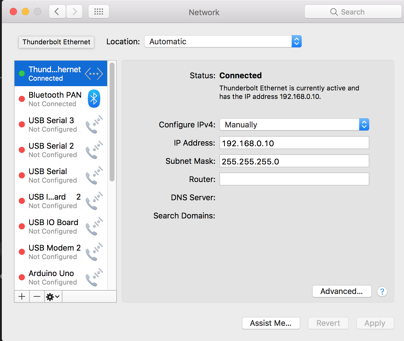
- Open your network preferences.
- Make sure your ethernet is connected
- Turn off wifi
- Select the appropriate network adaptor (will say something about ethernet)
- Set “configure IPv4” to “manually”
- Set your IP address to 192.168.0.10
- Set your subnet mask to 255.255.255.0
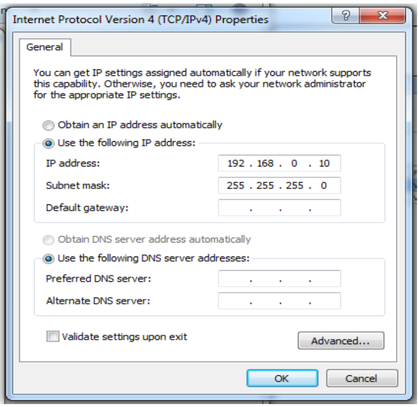
Windows
- Open your network preferences
- Set you IP address to 192.168.0.10
- Set your subnetmask to 255.255.255.0
- Turn off wifi
PixLite Setup
You should have already downloaded and installed the Advatek Assistant Software for macOS or Windows.
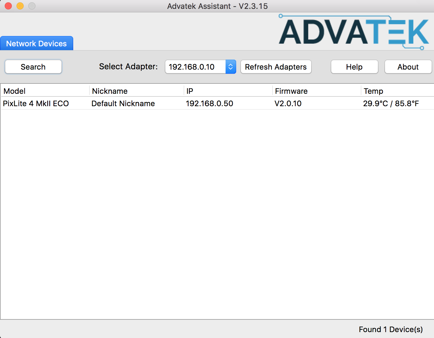
- Open the “Advatek Assistant” software.
- Change the “Select Adapter” to 192.168.0.10
- Click the “Search” button (make sure the green “power” light on the PixLite is solid)
- You should see the PixLite 4 unit become visible. Double click it.
- Go to the “LEDs” tab in the popup and change the “Pixel IC” to “WS2811”
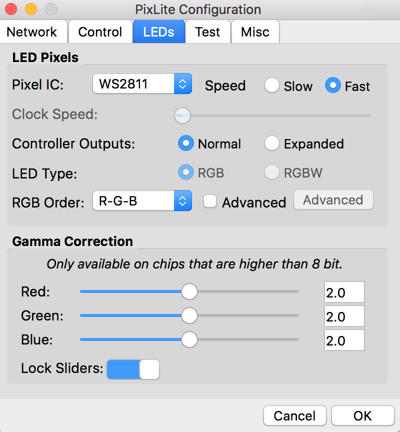
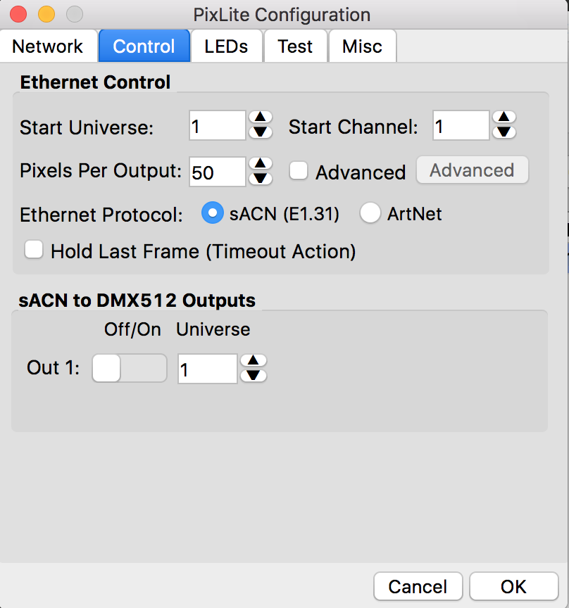
- Go to the “control” tab and make sure the Universe is
1, Start Channel is1and Pixels Per Output is50 - Click the “OK” button. This will restart the PixLite unit.
- Allow the PixLite to fully reboot. (green light will stop blinking).
- Research for the unit and select it.
- Go to the “test” tab, change the “Set Test” menu to “Set Color” and click “Set”
- Move the color picker around and you should see all of the LEDs change accordingly.
TouchDesigner Again
After communication with the PixLite unit is established and confirmed through the Advatek Assistant, go back to TouchDesigner and set the “Active” parameter of the pixelMapper to “ON”