TouchDesigner + Arduino
Download the td_firmata.toe file from the TouchDesigner Examples folder on Google Drive.
Download and install the Arduino IDE. Select the correct download for your operating system under the “Download the Arduino IDE” section.
What is Arduino
The Arduino ecosystem consists of any Arduino-compatible microcontroller and the Arduino IDE software. It was designed to allow non-engineers to program and work with microcontroller hardware in an easy-to-implement way; avoiding the often complicated processes that existed before. The the purpose of this tutorial, we will call any Arduino-compatible microcontroller an “Arduino”
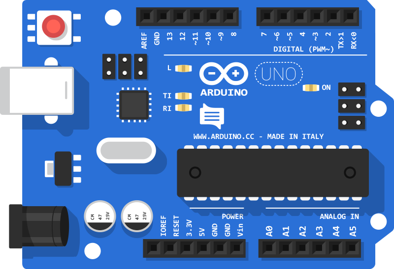
Anatomy of an Arduino Board

Analog Pins
Arduinos contain any number of “Analog Pins”, each of which contains an “Analog to Digital Converter” or “ADC”. These pins allow us to read the physical world and convert what it’s read into a number betwee 0-1023. We use the analog pins to read from sensors such as potentiometers, pressure sensors, light sensors and any other sensor that outputs a variable voltage between 0 and 5 volts.
Digital Pins
Digital Pins can act as and OUTPUT or INPUT. We can use them to drive LEDs (OUTPUT mode) or to sense if a switch or button has been pressed (INPUT mode).
In OUTPUT mode, Digital Pins can only turn HIGH or LOW, which is another name for ON and OFF or 1 or 0. In Arduino syntax, this is done using the digitalWrite(PIN, VAL) function and passing in a 1 or 0. So if we wanted to turn pin number 7 ON, we would use digitalWrite(7, HIGH).
Some pins on the Arduino can also perform “PWM”, which is a technique that allows us to toggle the digital pin very quickly. We can use PWM to control the brightness of an LED or the speed of a DC motor. The Arduino has “8-bit PWM”, which means we can control the PWM using a number between 0-255. A value of 0 means that the PWM will be all the way off and a value of 255 means the PWM will be all the way on. The diagram below demonstrates how PWM works:

In Ardino syntax, this is done using the analogWrite(PIN, VALUE) function. So if we wanted to set an LED connected to pin number 6 to 50%, we would write analogWrite(6, 177).
Digital Pins also all us to “read” the outside world, similar to the Analog Pins. Digital Pins, however, can only read an “ON” or “OFF” state. We use Digital Inputs to read from buttons and switches. In Arduino syntax, this is done using the digitalRead(PIN) function. So if i wanted to know the state of a physical button (whether it was up or down) I would use boolean button = digitalRead(7);. The variable button would then store the on/off state of the physical button connected to pin 7.
Power Pins
Arduinos also have a series of “power pins”. On the Arduino UNO and similar clones (which we are using in class), these power pins include a 5v pin and a GND pin. Those stand for “5 volts” and “Ground”.
Other Pins
Arduinos also contain a few other pins that are used to communicate with more advanced components over protocols such as i2c and SPI. For more information on using i2c with Arduino, check out this page. And for more information on using SPI with Arduino check out this page
Firmata
Firmata is a large piece of Arduino code that, when uploaded to the Arduino, allows users to control the Arduino directly from a computer without writing new code in the Arduino IDE. We will be using Firmata for much of the Arduino + TouchDesigner work we do in class.
Install Firmata
- Open the Arduino IDE on your computer
- Connect your Arduino to your computer using a USB cable.
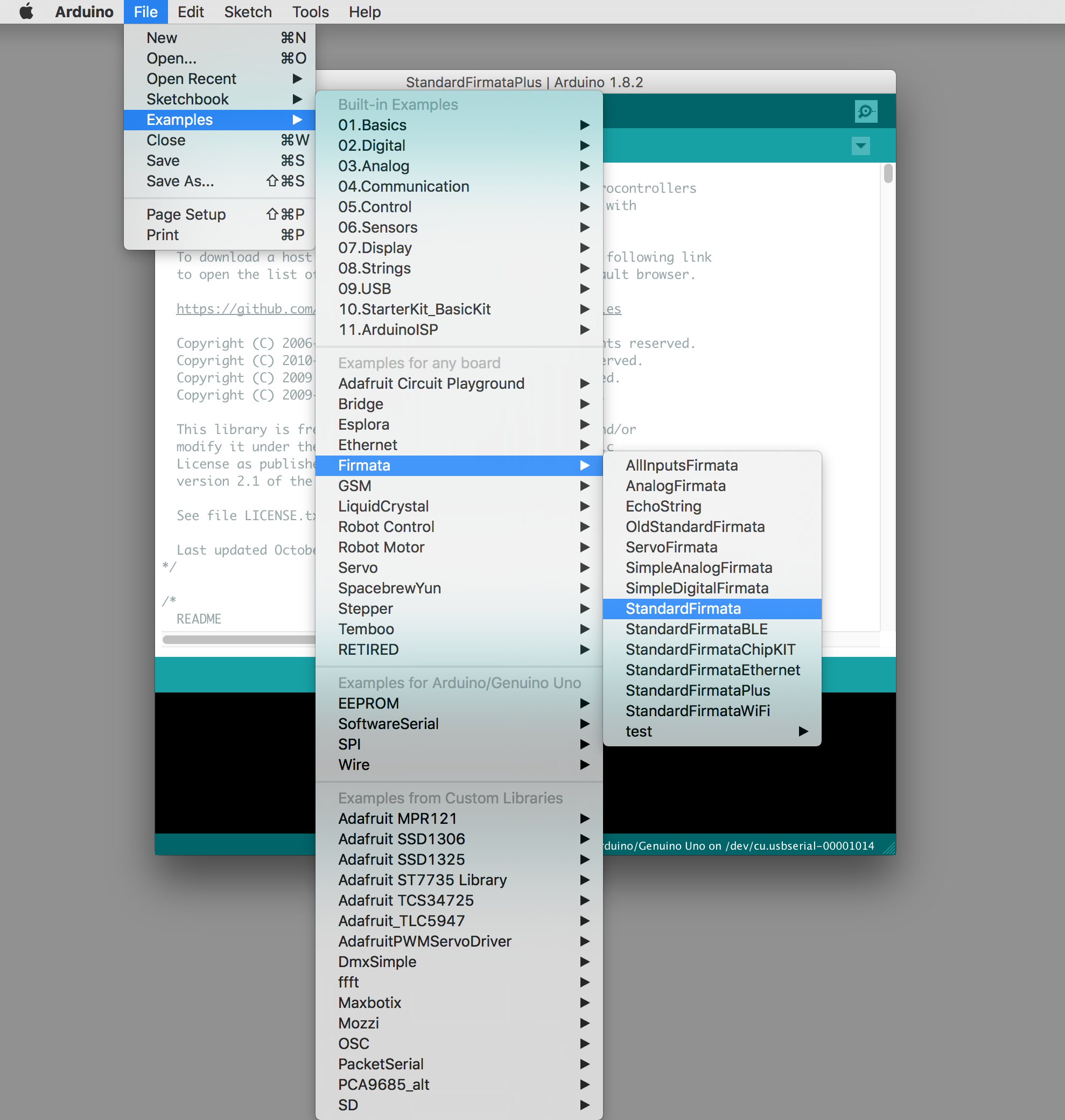
- In the IDE menu, select
Files>Example>Firmata>StandardFirmata - In the IDE menu, select the type of Arduino Board you are using
Tools>Board. For these examples, we are using the “Arduino/Genuino Uno” - In the menu, select which USB port you are using.
Tools>Port - In the Arduino window, click the arrow button to upload the StandardFirmata to your board.
TouchDesigner + Firmata
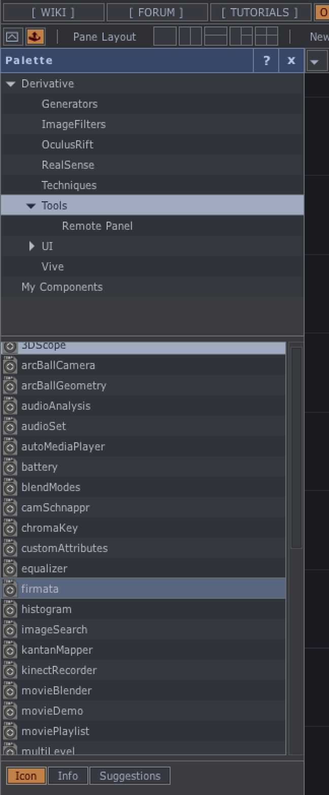
TouchDesigner has built-in functionality that allows us to easily interface with the Arduino using Firmata. To begin, we need to open the Palette inside TD. Find the “firmata” under the “Tools” section. Click and drag the “firmata” item onto the network editor.
This should create a COMP called “firmata”. This COMP, and its parameters, will be our tool for interfacing with the Arduino. The parameters section has three tabs that we need to work with: firmata, Pin Modes, and Pin Values. Lets start with the firmata tab:
Parameters
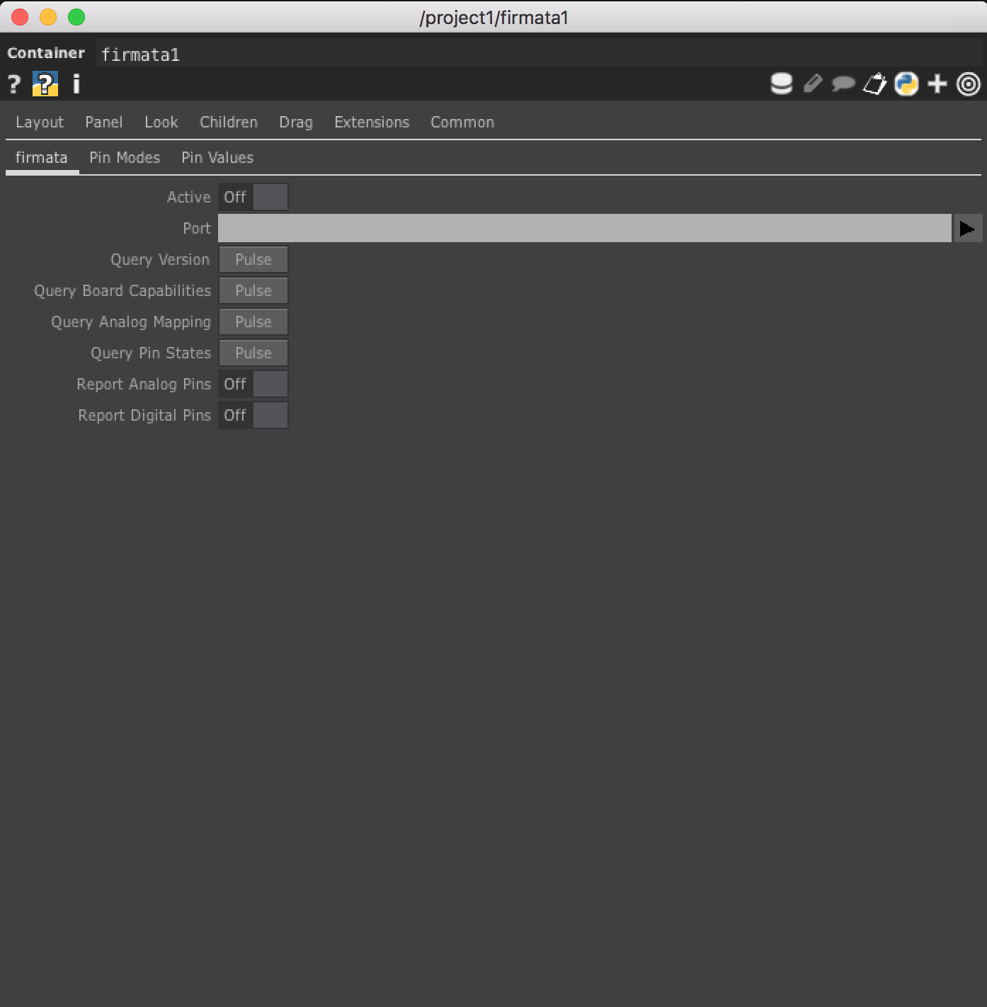
- Select the
portthat your Arduino is connected to. This is the same Port that you selected in the Arduino IDE when you uploaded Firmata. - Turn the
Activebutton toon - Turn
Report Analog PinsandReport Digital Pinstoon
Next, select the Pin Modes tab.
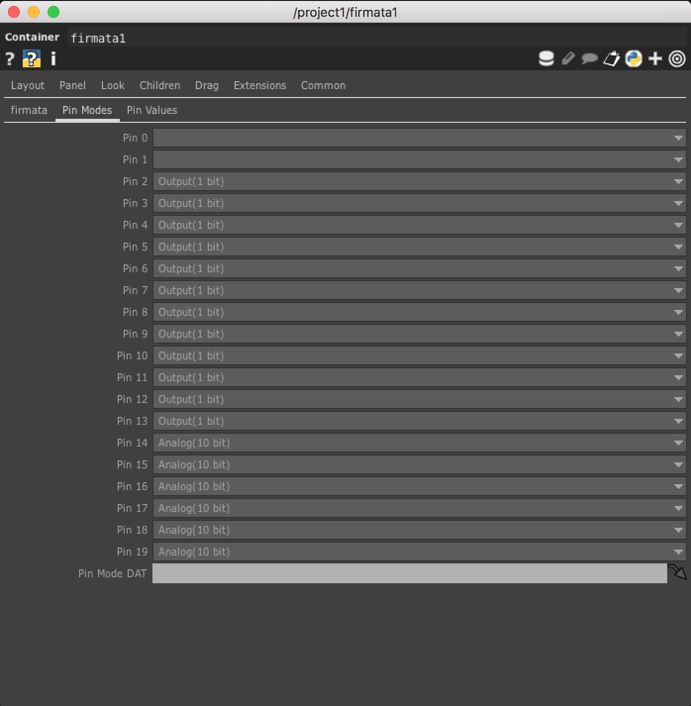
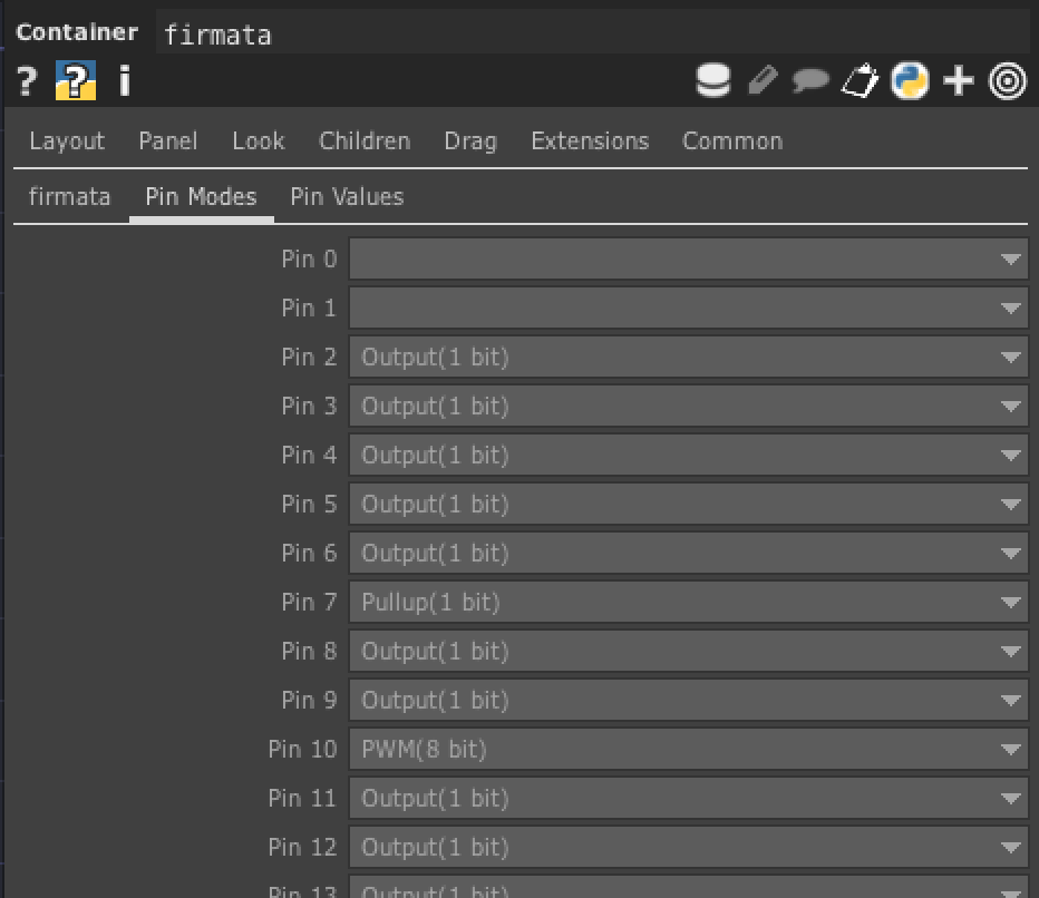
This is where we set the functionality of each pin. We can choose if we want a pin to be Input(1 bit), Output(1 bit), Pullup(1 bit), PWM(8 bit) or Servo(14 bit).
Input(1 bit): This is our “digital read” functionality. we use this to read from physical buttons or switchesPullup(1 bit): This is a modified version of “digital read” in which the pin is “ON” by default. This is a preferred way of working with physical buttons, as it requires less physical wiring.Output(1 bit): This is our “digital write” functionality. We use this to turn the pin ON and OFFPWM(8 bit): This is our “analog write” functionality. We use this to control the brightness of LEDs or the speed of small DC motors.Servo(14 bit): Ideally you can control Servo Motors from this, but documentation is sparse and untested.
Next, select the `Pin Values’ tab.
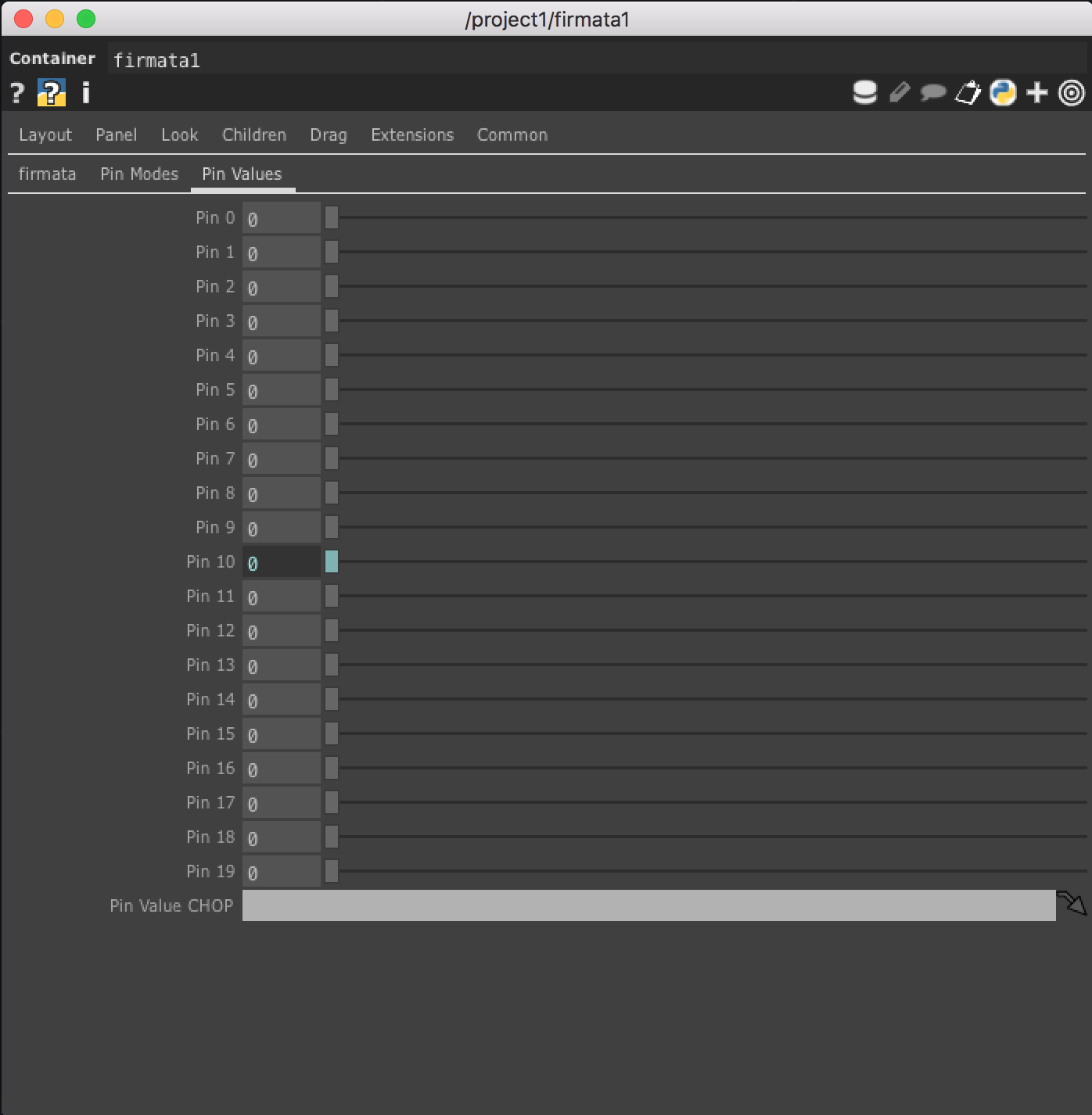
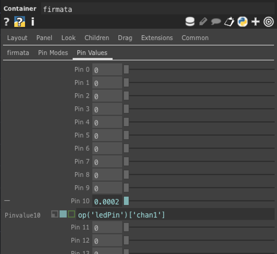
This is where we can directly control the Arduino Pins. In order to make this work, we need to make sure the pin we want to control has been set to either Output(1 bit) or PWM(8 bit) in the Pin Modes tab. We can then use our CHOP references to control the value of a pin by referencing a channel on a CHOP in our network.
Outputs

The firmata COMP has two outputs that we will use to extract data from the Arduino. There are several outputs on this COMP, two of them are green and the rest are purple. The green color means that they should connect to a CHOP and the purple color means the output should connect to a DAT. We want to see the data in CHOP form. Connect a Null CHOP to the first (top) green output and another Null CHOP to the second green output. The first green output tells us the values coming in off of the Analog Pins and the second green output tells us the values coming in off of the Digital Pins that have been set to Input(1 bit).
Test Circuit
Setting up the Circuit
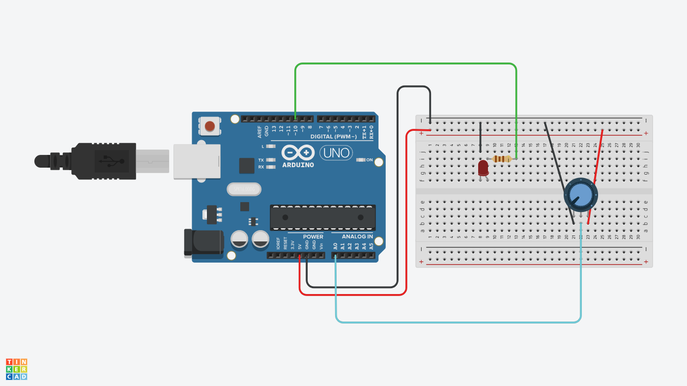
For this circuit you will need:
- An Arduino
- A breadboard
- An LED
- A 110 Ohm resistor
- A potentiometer
- hook-up wires
Using the components above, create the circuit in the image. Make sure all of your wires are connected correctly.
Pro Tip: LEDs are polarized meaning they only allow electricity to flow in one directly. If you connect it the wrong way, it might burn out. LEDs often have a small notch on the side of the plastic cover. The notch indicates the “cathode” or the side that connects to ground.
Some things to note here: We have connected the potentiometer to analog pin A0 on the Arduino and we have connected the LED to digital pin 10 on the arduino.
Setting up TouchDesigner firmata Panel
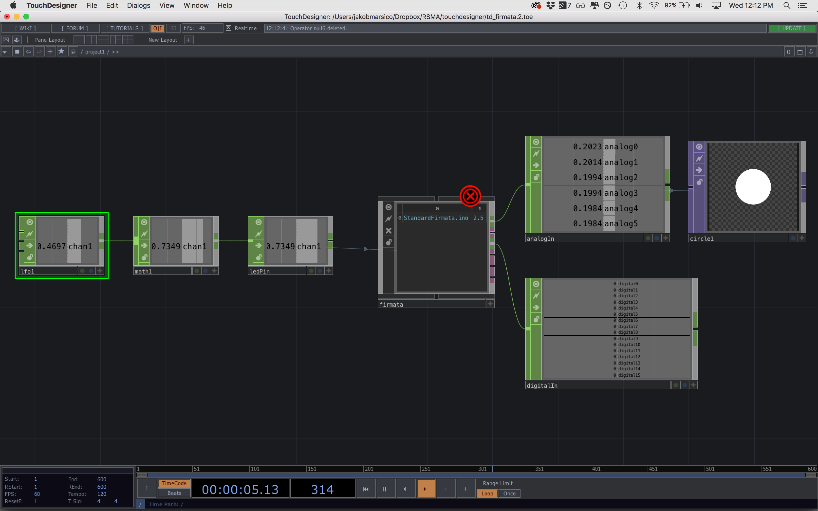
Set up a network in Touchdesigner that looks like the one above. We have the following operators:
- LFO CHOP
- Math CHOP - set the range (from -1 to 1) and (to 0 to 1)
- Null CHOP - rename this null CHOP to
ledPin
In the firmata COMP’s panel, go to the Pin Modes tab and change Pin 10 to PWM(8 bit). Next, go to the Pin Values tab and make a reference to the single channel in the ledPin CHOP.
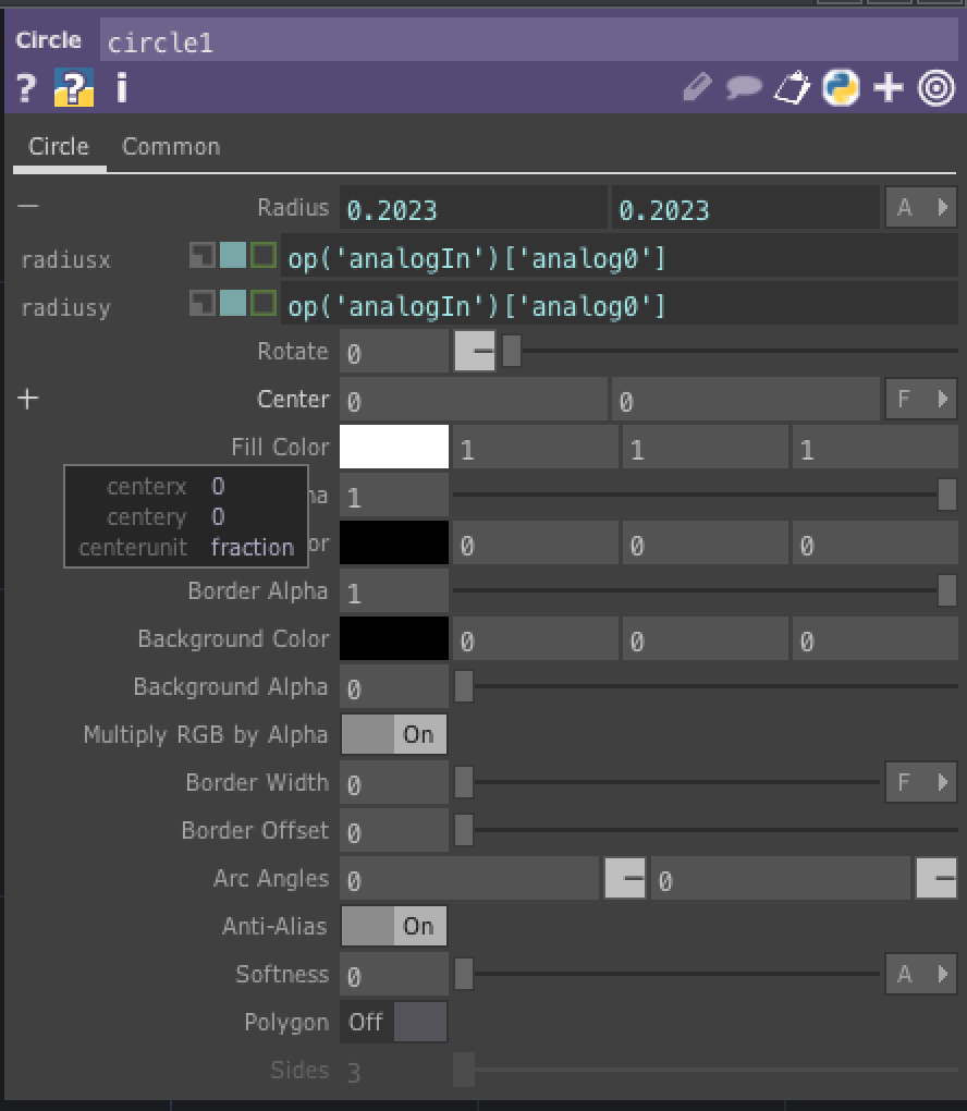
To get data from the Arduino, let’s connect a Null CHOP to the top output of the firmata COMP. This should show us our incoming analog values. Create a circle TOP. In the TOP’s panel, use a reference to the first channel of the output CHOP to change the radius of the circle.
